Ignition
The Factory Shop Manual tab below provides data on how the ignition systems piece of work, how to exam them, and how to repair them. The Crane Cams tab provides information on what the different timing mechanisms exercise & how to change them to re-bend a distributor. In addition, Scotty Johnson, The Mad Porter, has instructions on his web site for re-curving a distributor: Page 1 & Page 2 . (Yes, I know you can get to Page ii from Folio i, but it isn't obvious.)
This document is from the 1980 factory shop manual section on Engine Diagnosis & Service:
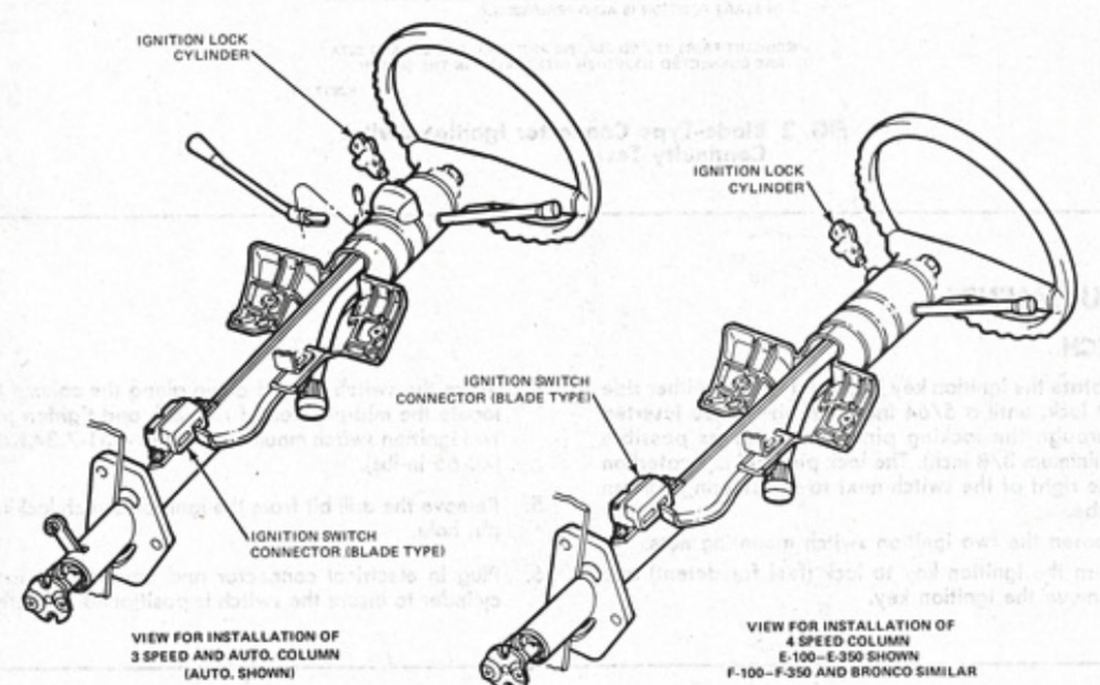
The ignition switch on these trucks can cause a number of bug. In fact, what most people think of as the switch, the affair into which you put the fundamental, is actually only the ignition lock cylinder. The switch itself sits lower on the column, as shown in the illustration beneath:
One of the issues trucks of this historic period oftentimes have with the switch is that the lubrication has set upward and the cardinal doesn't render from Start fully into Run. In this case the turn signals, clock, and several other items won't work properly, and then this is a good tip off of the problem. This seems to happen most often when the weather gets cold and the lubrication sets upward. If this is the example with your truck, try lubricating the lock cylinder and the link going to the switch. If that doesn't assistance then cleaning and lubricating the switch itself may be in social club, and to do that a cleaner/lubricant like one fabricated for Boob tube tuners or radio controls works well. Removal:
- Disconnect the battery ground cable
- Remove the steering column shroud and lower the steering cavalcade
- Disconnect the switch wiring at the multiple plug
- Remove the two nuts that retain the switch to the steering column
- Lift the switch vertically upward to disengage the actuator rod from the switch and remove the switch.
Installation:
- When installing the ignition switch, both the locking mechanism at the superlative of the column and the switch itself must be in LOCK position for right adjustment. To hold the mechanical parts of the cavalcade in LOCK position, move the shift lever into PARK (with automatic transmissions) or REVERSE (with manual transmissions), plough the key to LOCK position, and remove the key. New replacement switches, when received, are already pinned in LOCK position past a metallic aircraft pin inserted in the locking hole on the side of the switch. To insert a pin in a used switch refer to Adjusting.
- Appoint the actuator rod in the switch.
- Position the switch on the column and install the retaining nuts, but do not tighten them.
- Motion the switch up and down along the column to locate the mid-position of rod lash, and and so tighten the retaining basics.
- Remove the locking pin, connect the battery cable, and check for proper outset in PARK or NEUTRAL. Besides check to brand certain that the start circuit cannot be actuated in the DRIVE and Opposite position.
- Raise the steering cavalcade into position at the instrument panel (Part 13-06). Install steering column shroud.
Adjusting:
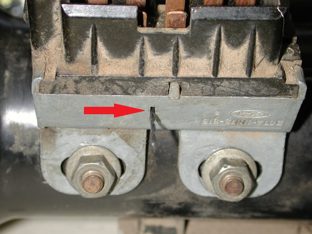
- Rotate the ignition key back and forth to either side of lock, until a #56 (.0465") drill bit can be inserted through the locking pivot hole as far as possible (minimum 3/8"). (Annotation: I found that a .053" sewing needle is a perfect fit.) The lock pivot hole is located on the right of the switch next to the steering column tube. See instructions and pictures, beneath.
- Loosen the two ignition switch mounting nuts.
- Turn the ignition key to lock (feel for detent) and remove the ignition primal.
- Motion the switch up and down along the column to locate the mid-position of rod lash and tighten the 2 ignition switch mounting nuts to 4.51-7.34 Nm (40-65 in-lbs).
- Remove the drill flake from the ignition switch locking pin hole.
- Plug in the electrical connector and operate the lock cylinder to ensure the switch is properly positioned.
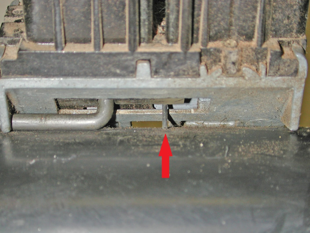
Lock Pivot:
Put the lock pivot (#56 or 3/64" drill bit) in from the left side of the switch, equally shown below, and gently move the switch'due south internals upwards and down until the pivot goes through the pigsty within and comes out on the correct side.
| | |
And, if you are testing an ignition switch, here are the pin-outs and continuity tests:
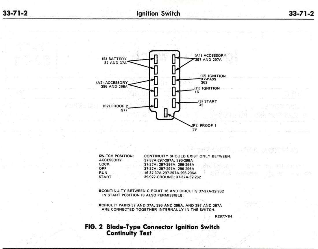
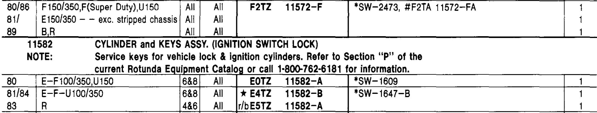
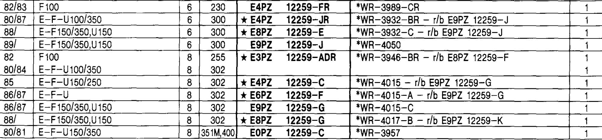
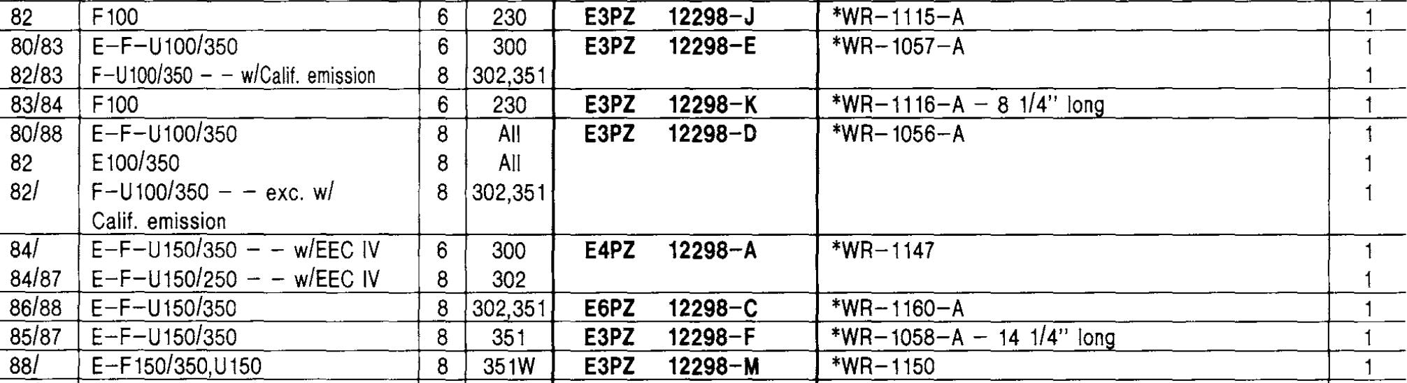
Finally, here are the function #'due south. Notation that the original switches for some trucks were marked E0TA-11572-B1B, but those were replaced past ones marked E4TA-11572-A.


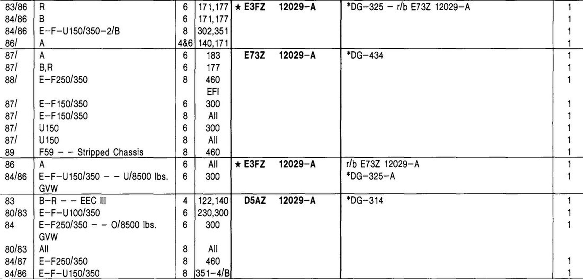
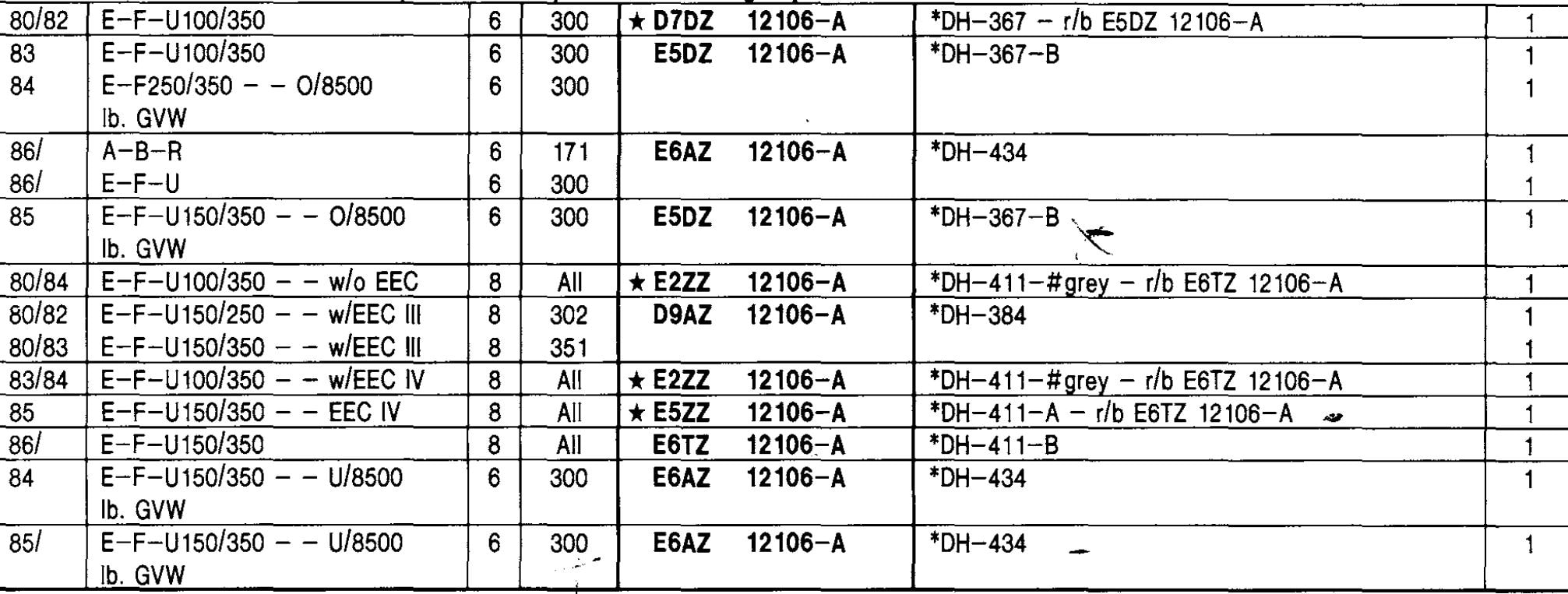
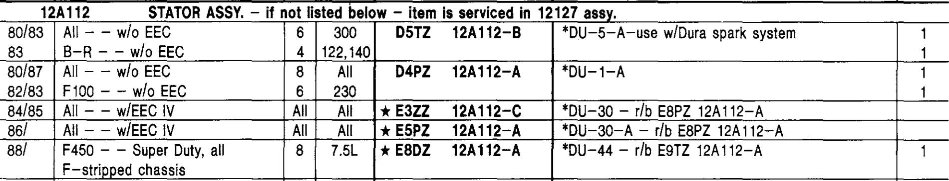
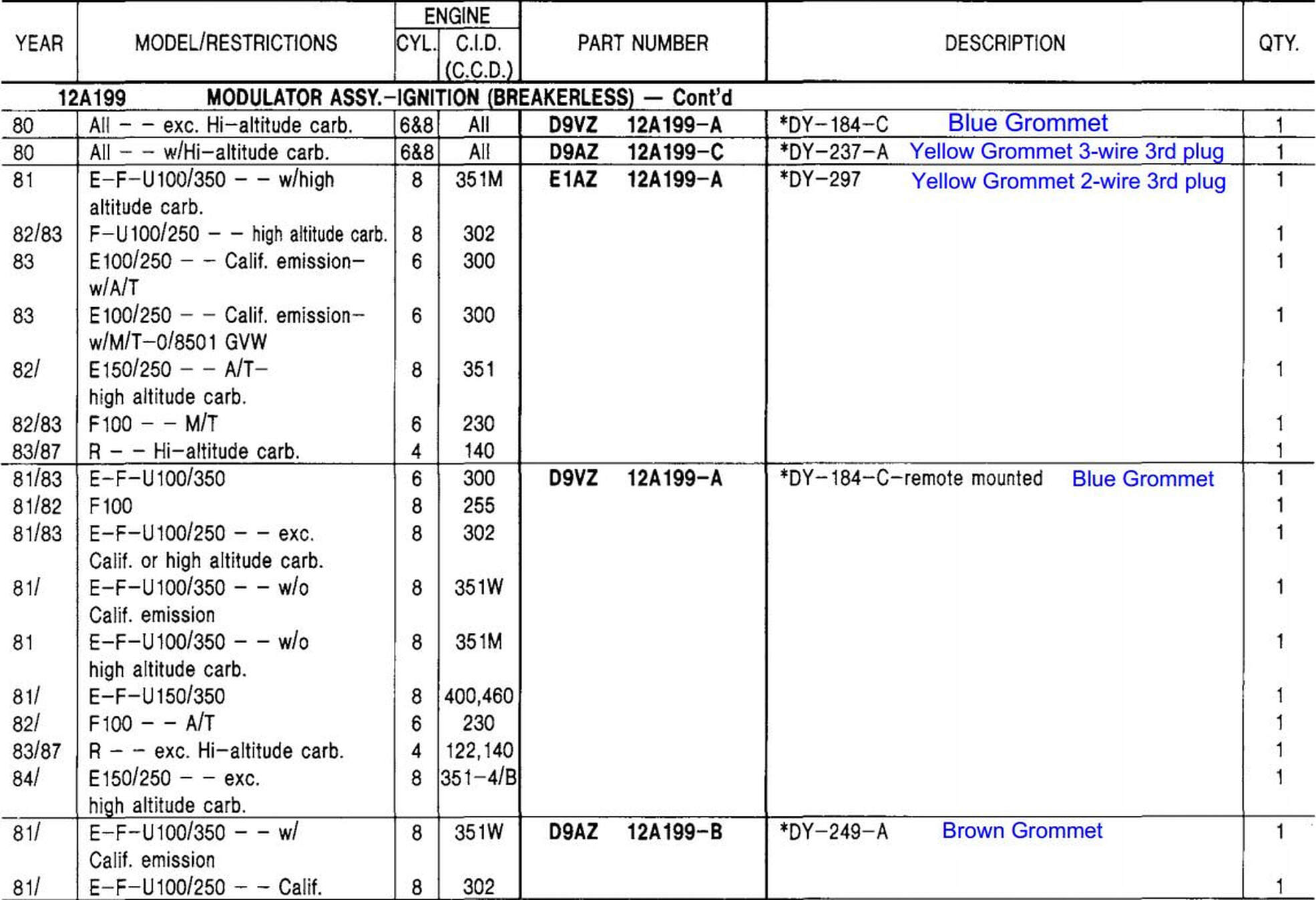
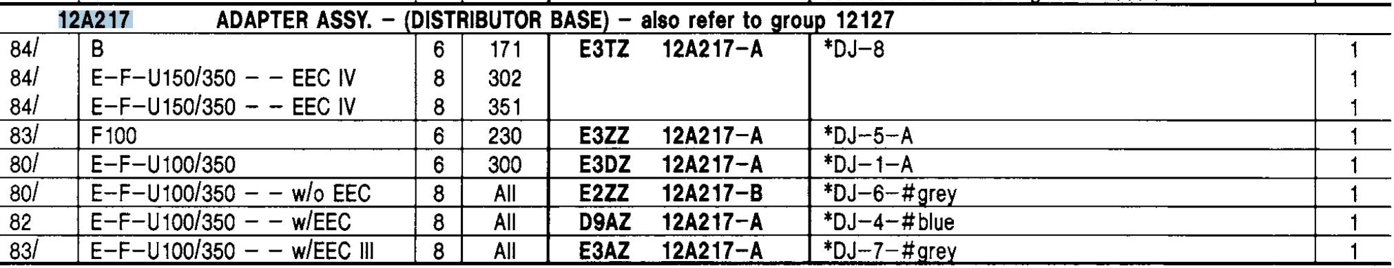
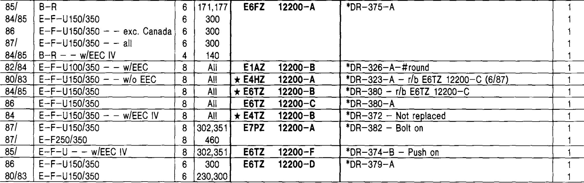
Listings of the ignition modules used on the 1980 - 86 Ford trucks. The data on the grommet colors was gleaned fromBob's Garage Library andBZEROB.com. My understanding is the blueish-grommet module was used without a computer, the EEC-III computer systems used the brown-grommet module, and the EEC-Iv calculator systems used the yellow-grommet modules with the 2-wire 3rd plug. I do not know with which reckoner system the 3-wire tertiary-plug yellow-grommet modules were used, simply if you exercise please edify me.


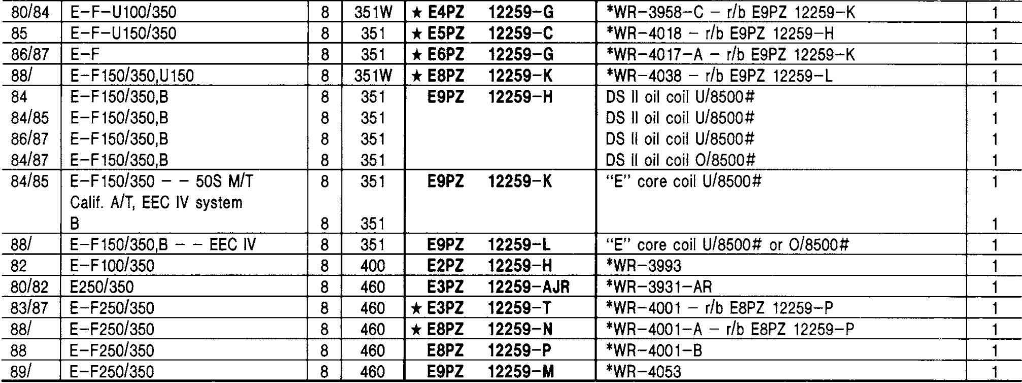

Many people are wanting to catechumen their trucks from Ford'south EEC-III or Iv ignition arrangement to something that doesn't crave a computer. Basically there are two means to do that - either convert to a DS-II ignition organisation or install a one-wire distributor, sometimes called an HEI or DUI. The tabs below mankind out how to do either of those approaches. But starting time, let's think through the advantages and disadvantages to either approach:
- DS-Ii
- Advantages:
- Common: With the exception of the wiring harness (see beneath), all of the parts are readily available at a parts store or salvage, then if information technology breaks in the back-of-beyond you tin can easily become back on the road.
- Plug-And-Play: If you find all the parts it is plug-and-play.
- Disadvantages:
- Wire harness: These are becoming harder to find in usable class. And the aftermarket ones are fairly expensive and don't necessarily fit well.
- Article of clothing: A used distributor can be badly worn. But, you can buy new DS-II distributors, and if that'southward done then this isn't a disadvantage.
- Advantages:
- Ane-Wire:
- Advantages:
- Advance bend: Many one-wire manufacturers dial in a curve for how yous tell them the engine volition be congenital.
- New: For the nearly role you'll be buying a new distributor
- Disadvantages:
- Rare: This is the flip-side of the DS-II in that you probably can't walk into any parts store and purchase a replacement distributor should yours exit yous on the side of the road.
- Wiring: As yous'll meet on the One-Wire tab, the wiring is fairly straightforward. All the same, you lot will accept to do some wiring as at that place is no kit that I'm aware of that makes this a plug-and-play.
- Quality: There are good ane-wire distributors and at that place are those that break quickly and often.
- Size: The HEI dizzy is much larger than the DS-II and that can cause bug with fitment.
- Advantages:

On the left below is the EEC wiring diagram from Ford'southward 1985 EVTM. While it is for the four.9L engine, all of the EEC ignitions were wired the aforementioned manner. The diagram shows the parts of the ignition organisation that you won't use if you are converting to a ane-wire distributor. And on the right is an example of how you could wire your truck for a one wire dizzy. (Click on either to get a larger diagram.)


The relay shown is a mutual "Bosch" fashion relay like
this aneon Amazon. Simply, it is going to demand some kind of weather protection to live under the hood. And, y'all will probably want to get a socket with pigtails to simplify the wiring, like
this aneon Amazon.
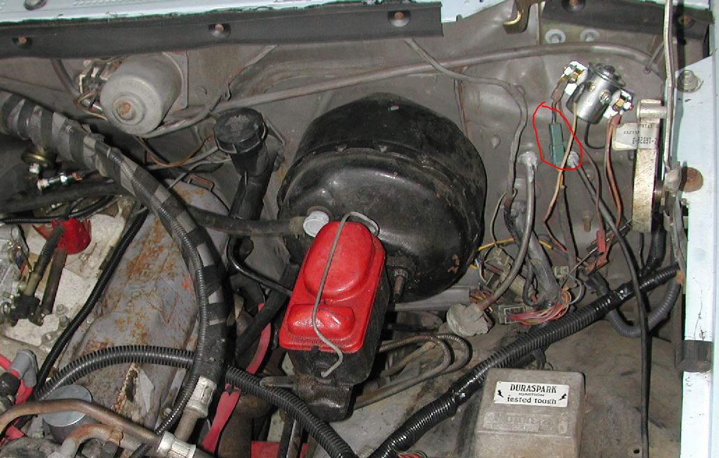
The pull-in voltage comes from the white/light blueish wire that was previously connected to either the curlicue or connector C321. The ability to a i-wire needs to be substantial since they require a lot of electric current, and should be at least a #12 wire. You can get that power from Excursion 37, which is a large yellow wire that is usually expressionless-concluded beneath the brake chief cylinder. If you have a factory auxiliary battery you'll have a relay on the firewall to the right of the chief cylinder, and Circuit 37 will exist connected to it, as shown below. Or, if y'all accept the trailering option or a DRW truck you may have a ability stud on the firewall with Circuit #37 connected to it. In whatever case you tin connect to that circuit to go battery power for the ignition. Even so, you should put a fuse, probably a 20a one, in the circuit as that wire uses a fusible link that is capable of far more current than you need for the one-wire benefactor.
Source: https://www.garysgaragemahal.com/ignition.html

Posting Komentar untuk "Ignition"